STANDARDS & SPECIFICATIONS
IN POLARIS® FENESTRATION PRODUCTS
When checking for defects, Polaris Windows & Doors® recommends the following steps in accordance with ASTM C1036:
SINGLE LITES UP TO 6 SQUARE FEET
Scratches - Viewable as stated above, must be 1" or less. No more than 1 is allowed per lite.
Debris, Dirt, Spots - Viewable as stated above, must be 1/16" or less. No more than 1 is allowed per lite.
Seeds, Bubbles, Knots, Stones - Viewable as stated above, must be 1/16" or less. No more than 1 is allowed per lite.
No more than 1 total viewable defect as described above is allowed per lite.
Shells - No more than ¼" from edge less than ½ the thickness of the lite. No more than 1 per side.
Chips - No more than ⅛" from the edge. No more than 1 per side.
Coating - Must be uniform on the lite inspected when viewed in transmission using the inspection criteria previously stated above.
The border area is comprised of 2 inches plus ½" from each edge of the lite. All other areas are the central area.
SINGLE LITES 6 TO 35 SQUARE FEET
SINGLE LITES OVER 35 SQUARE FEET
ALLOWABLE DEFECTS VISUAL AID
- Move away from the glass by stepping ten feet back.
- Face the glass straight on at 90°.
- View in the daylight but not in direct sunlight or direct applied light.
- Inspect the central 80% of the glass (examples shown below).
- Inspection should not exceed viewing of more than the following in transmission or reflection:
- 5 seconds for lites up to 6 square feet.
- 10 seconds for lites up to 35 square feet.
- 20 seconds for lites greater than 35 square feet.
SINGLE LITES UP TO 6 SQUARE FEET
SINGLE LITES 6 TO 35 SQUARE FEET
- Scratches - Viewable as state above, must be 1" or less. No more than 2 are allowed per lite and must be separated by a minimum of 24 inches.
- Debris, Dirt, Spots - Viewable as stated above, must be 1/16" or less. No more than 2 are allowed per lite and must be separated by a minimum of 24 inches.
- Seeds, Bubbles, Knots, Stones - Viewable as stated above, must be 1/16" or less. No more than 2 are allowed per lite and must be separated by a minimum of 24 inches.
- No more than 2 total viewable defects as described above are allowed per lite.
- Shells - No more than ¼" from edge, less than ½" the thickness of the lite. No more than 1 per side.
- Chips - No more than ⅛" from the edge. No more than 1 per side (See illustration for chips).
- Coating - Must be uniform on the lite inspected when viewed in transmission using the inspection criteria previously stated above.
- The border area is made up of 4 inches plus ½" from each edge of the lite. All other areas are the central area (see illustration).
SINGLE LITES OVER 35 SQUARE FEET
- Scratches - Viewable as state above, must be 1" or less. No more than 3 are allowed per lite and must be separated by a minimum of 24 inches.
- Debris, Dirt, Spots - Viewable as stated above, must be 1/16" or less. No more than 3 are allowed per lite and must be separated by a minimum of 24 inches.
- Seeds, Bubbles, Knots, Stones - Viewable as stated above, must be 1/16" or less. No more than 3 are allowed per lite and must be separated by a minimum of 24 inches.
- No more than 3 total viewable defects as described above are allowed per lite.
- Shells - No more than ¼" from edge, less than ½" the thickness of the lite. No more than 1 per side.
- Chips - No more than ⅛" from the edge. No more than 1 per side (See illustration for chips).
- Coating - Must be uniform on the lite inspected when viewed in transmission using the inspection criteria previously stated above.
- The border area is made up of 6 inches plus ½" from each edge of the lite. All other areas are the central area (see illustration).
ALLOWABLE DEFECTS VISUAL AID
-
Type 1 (Transparent Flat Glass) - Chips on the glass edges shall be viewed at a proximity of 12" without magnification, using localized lighting.
- Shell Chips*: Shell chips are permitted within the requirements shown in Table 3, if there are no associated cracks, detectable without magnification, as viewed from the edge.
- Chip depth ≤ 50% of glass thickness.
- Chip width ≤ glass thickness or 6mm (¼"), whichever is greater.
- Chip length ≤ 2 times the chip width. * Taken from ASTM C1036-21 Table 3 Allowable Shell Chip Size and Distribution for Cut Size and Stock Sheet Qualities of Type 1 —Transparent Flat Glass (Quality-Q3) Type 1, Class 1 and 2 glass as specified by Section 4 Classification and Intended Use.
- V-Chips are not permitted.
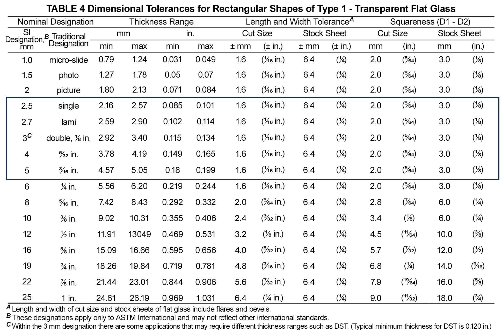
- Dimensional Tolerances for length, width, squareness, and thickness for rectangular shapes shall use the tolerances in accordance with ASTM C1036-21 Table 4.
- Insulated glass unit allowable size variance per glass thickness:
- 3/32" (2.5mm) = (+/-) 1/16"
- 1/8" (3mm) = (+/-) 1/16"
- 5/32" (4mm) = (+/-) 1/8"
- 3/16" (5mm) = (+/-) 1/8"
- Glass Alignment offset in the width or height of the unit to be 1/16" or less.
- Overall unit thickness to be as follows:
- Annealed: Double = [+0.010": -0.015"]; Triple [+/- 0.030"].
- Tempered: Double = [+0.020": -0.030"]; Triple [+/- 0.030"].
- Bowed Spacer - Out: The master spacer must not extend beyond the edges of the glass anywhere, even if covered by sealant.
- Sealant squeeze out of sealant past the edge of the IG unit is acceptable up to 1/16". Amounts over 1/16" can make it difficult to insert the IG unit into a sash.
- Intercept (desiccated matrix):
- Waviness up to 1/8" is acceptable.
- Incidental mark (blemish) up to 1/8" is acceptable.
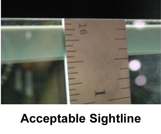
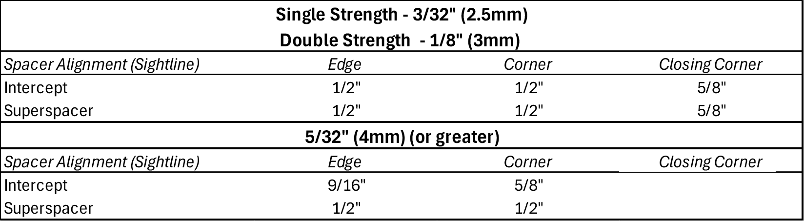
- Spacer alignment sightline:
- Sealant may extend beyond the spacer into the unit but should not exceed sightline specifications.
- Wet out may vary more in width on tempered units but should not be less than 3/16".
- Butyl or matrix balls on the spacer lip which may fall into the unit are not acceptable.
- Excessive hold down roller marks or other markings on th elip may be cause for rejection.
- Waviness in Superspacer material up to 1/8" is acceptable if sightline is not violated.
- Gap at closing corner up to 1/16" is acceptable.
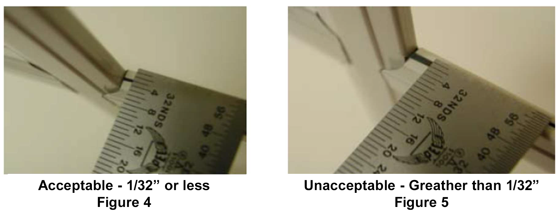
- Sealant Squeeze-Out
- Sealant past the edges of the IG unit can make it difficult to insert the IG unit into a sash:
- Squeeze-out of sealant less than or equal to 1/16" is acceptable.
- Squeeze-out of sealant over 1/16" is unacceptable.
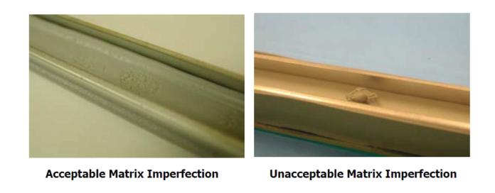
- Acceptable:
- Waviness up to ⅛" amplitude.
- Incidental mark (blemish) in matrix up to ⅛".
- Unacceptable:
- Waviness over ⅛" amplitude.
- Incidental mark (blemish) in matrix over ⅛".
- Loose matrix balls.
- Move away from the glass by stepping 10 feet back.
- Face the glass straight on at 90°.
- View in daylight but not in direct sunlight or direct applied light.
- Inspect the central 80% of the glass (examples shown below).
- Inspection should not exceed viewing of more than the following in transmission or reflection:
- 5 seconds for lites up to 6 square feet.
- 10 seconds for lites up to 35 square feet.
- 20 seconds for lites greater than 35 square feet.
- Hazing: A minimal amount of haze is inherent in insulating glass units (IGU) utilizing Low-E coatings and is NOT a defect. Haze occurs because tiny amounts of light are scattered from the glass and coatings, causing a small amount of glare.
- Localized Warp
- Localized warp for rectangular glass shall not exceed 1/16" over a 12" span.
- Tong Kink
- Any localized kink centered at any tong location shall not exceed 1/16" in a 2" span.
- Point Blemishes (dirt, debris, residue, pinholes, spot, fingerprint, etc.)
- Maximum size of 3" and a minimum of 24" between blemishes if seen at a distance of 10 feet.
- Bow
- Deviation in flatness spanning the entire pane of glass. Commonly seen in tempered glass and insulated Glass Units (IGU). This is not measurable as positive and natural deflection is a natrual occurrence with seasonal and barometric pressure cycling.
- Distortion
- Localized deviation in flatness that can look like ripples across the glass, or pockets of indentations. Allowed and quite common in tempered glass. Not measurable on site or in an Insulated Glass Unit.
- Strain Pattern
- An optical effect that results from the tempering process appearing as a pattern of dark spots on the glass. The intensity of the issue increases when viewed as steep angles to the glass and with polarized sunglasses. This optical issue is characteristic of tempered glass and cannot be completely controlled. It will vary from pane to pane.
- Fringes
- An optical effect that appears as a faint, random pattern resembling an oil stain. This is the result of having exactly matched thickness of glass panes in an IGU (less than .0001" difference in thickness).
- Sightline Infringement
- Allowable ⅛" maximum of an extension into the daylight opening of an Insulated Glass Unit by the sealant, spacer, or area of coating deletion.
- Condensation / Fogging / Newton Rings
- Allowable when:
- Outdoor condensation or frost occurs on the exterior side of the glass. This occurs when the glass temperature falls below the dew point, a clear night sky, still air, high relative humidity. Like dew on lawns and frost on automobiles.
- Indoor condensation or glass sweating on the room side surface of the glass. This typically occurs during the wintertime when there is high humidity inside of the room and the indoor glass temperature is below the dew point of the room side air.
- Defective when:
- Airspace condensation (between the panes of glass). Insulating glass units experiencing condensation in the airspace are usually due to a failure of the insulating glass seal. Airspace condensation can also be caused by a small crack in the glass that is sometimes not immediately evident. The outdoor and indoor glass surfaces should be cleaned to make certain the condensation is in the airspace and not on the outdoor and indoor glass surfaces.
- Needs to be Evaluated when:
- Condensation (Newton) Rings on the Indoor Glass Surface Condensation. Condensation rings occur when the glass lites touch in the glass center because there is a reduced insulating value, and the indoor glass temperatures are closer to the outdoor glass temperatures. This increases the potential for condensation on the room side pane and becomes evident when the room side glass temparatures fall below the dew point temperature of the room side air. The condensation only occurs in the center of the glass because the spacer keeps the edges of the glass apart maintaining the airspace's insulating properties.
INTERCEPT NOTES
SUPERSPACER NOTES
UNACCEPTABLE SQUEEZE-OUT
ACCEPTABLE SQUEEZE-OUT
DESICCATED MATRIX ON INTERCEPT SPACERS
When checking for defects, Polaris Windows & Doors® recommends the following steps in accordance with ASTM C1036:
-
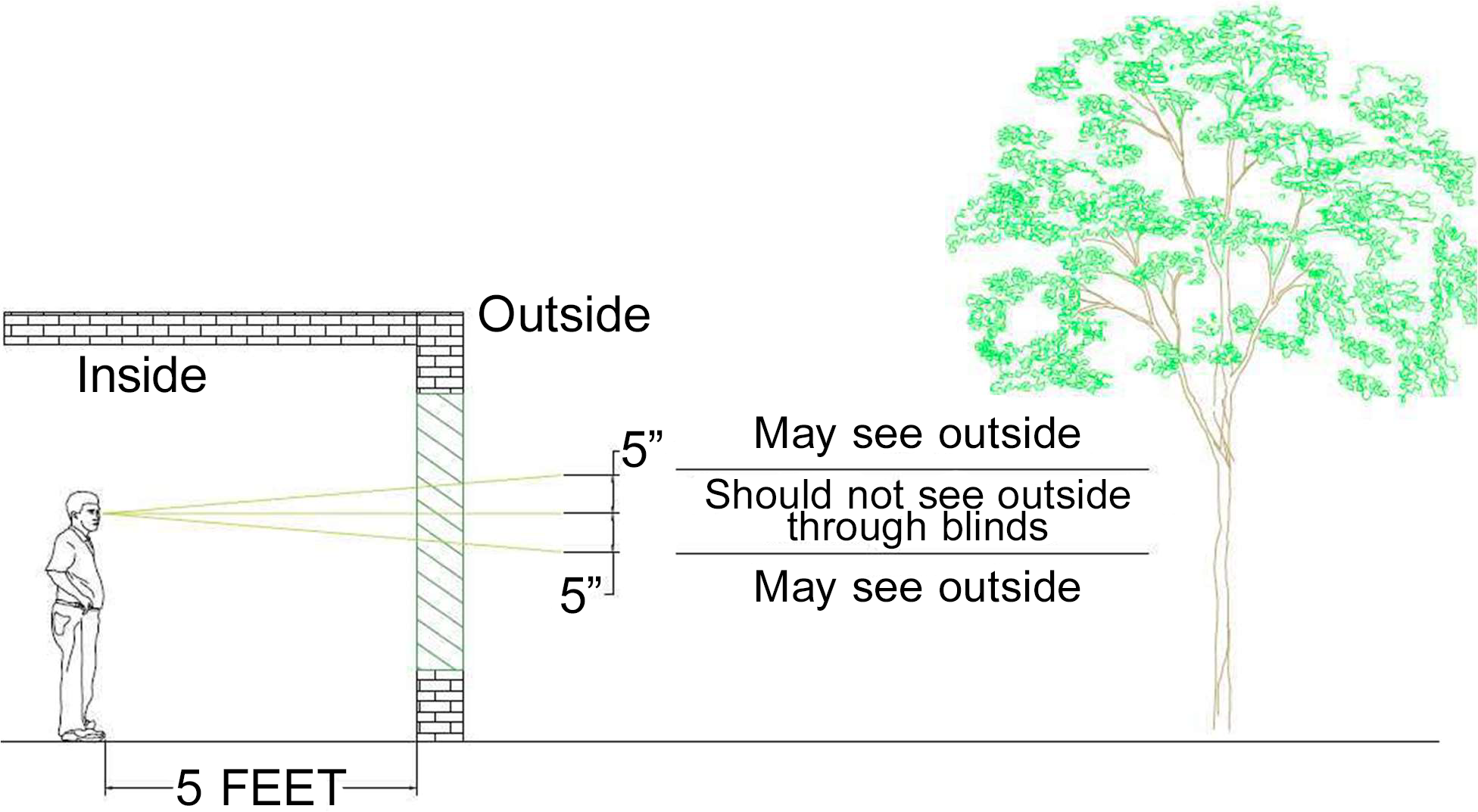
Venetian blinds between glass (BBG) units are sold as Sun Shading Devices and not Privacy Blinds. Important facts regarding BBG units:
- A small amount of daylight will be seen during the day around the blind, edges/slats or through the ladder holes.
- When viewed from the outside, they will not completely block vision of the interior as a small amount of vision can be seen when near the BBG unit around the slats, when looking at the same angle as the slats are tilted or through ladder holes.
- Tilt Only BBG is a blind system that uses an externally mounted magnetic control to adjust the tilt angle of the blind slats.
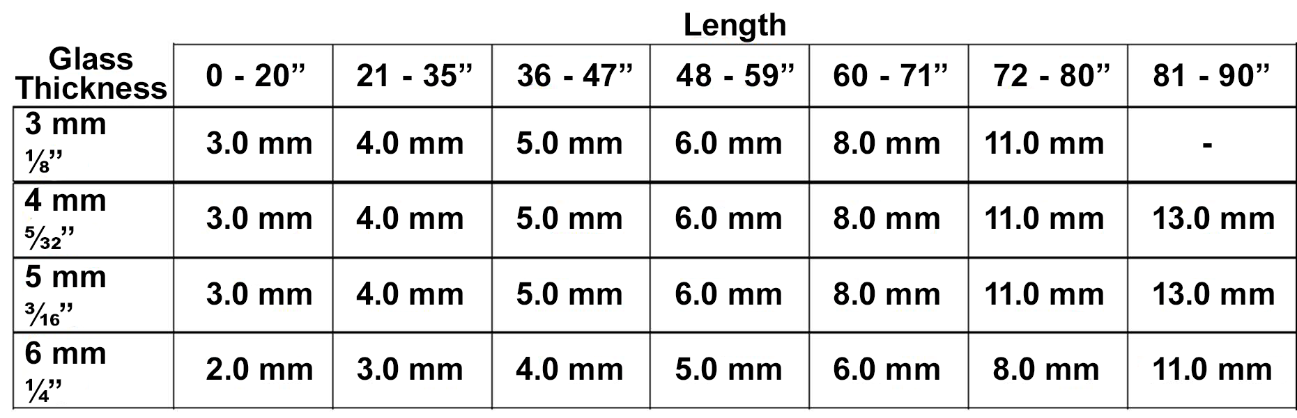
- Overall units' size (W x H)
- Glass thickness of ⅛" (3mm), 5/32" (4mm), and 3/16" (5mm) will have an allowable variance of (+/-) ⅛".
- Warp and Bow Tolerances - Units
- Overall Straightness
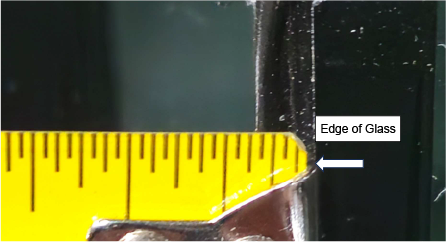
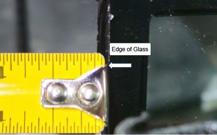
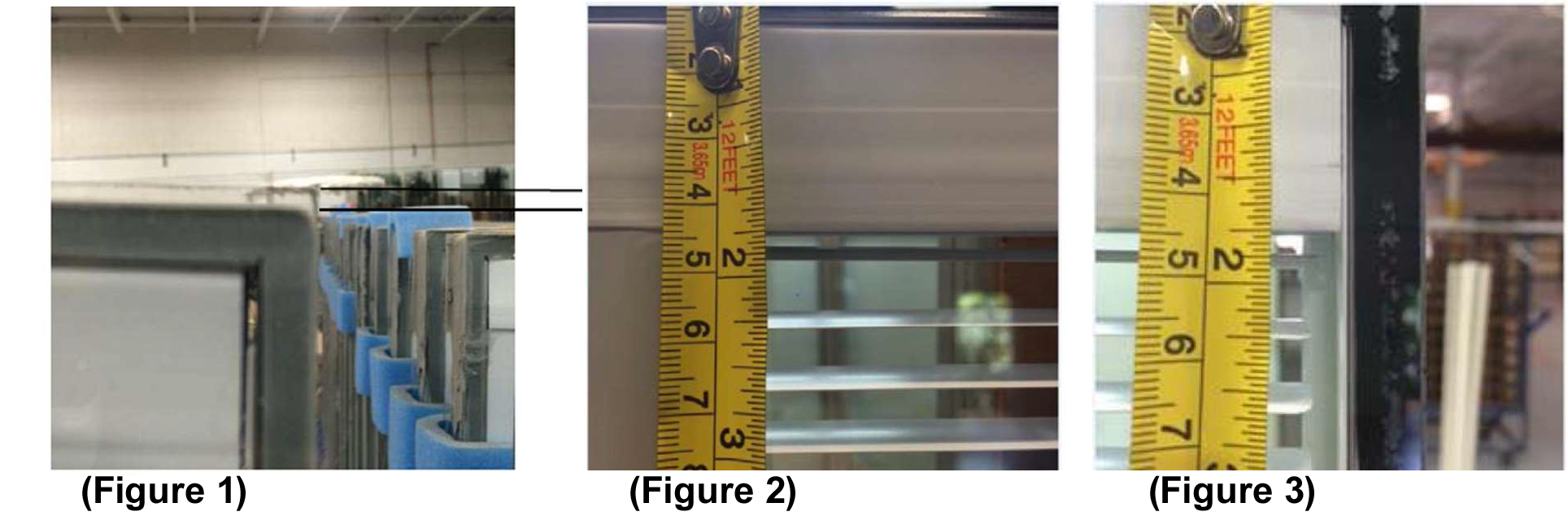
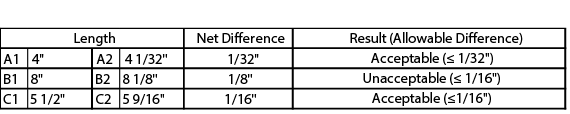
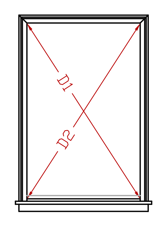
- Blinds are to be inspected visually first. Any blind that appears to be out of alignment shall then be measured using a tape measure. Blinds out of alignment are indicated by the location of the glass regarding how straight the sides are and how level the top is (Figure 1). Two measurements shall be taken for each blind slat that is questionable. Take measurements from the edge of the glass to both ends of the blind slat in question (Figures 2 & 3).
- Measurements shall always be taken beginning at the edge of the glass to the blind, not from blind to blind. The maximum differences between the two measurements given above shall be: 0.063" (1/16") for slats less than 12 inches long, 0.093" (3/32") for slats greater than 12 inches long.
- All visual inspection must take place from the units inside looking out position. Inspections shall be done for Tilt Only BBG in the down position and Lift and Tilt BBG in the down and open slat position.
- Unpainted end cuts of the blind are allowable.
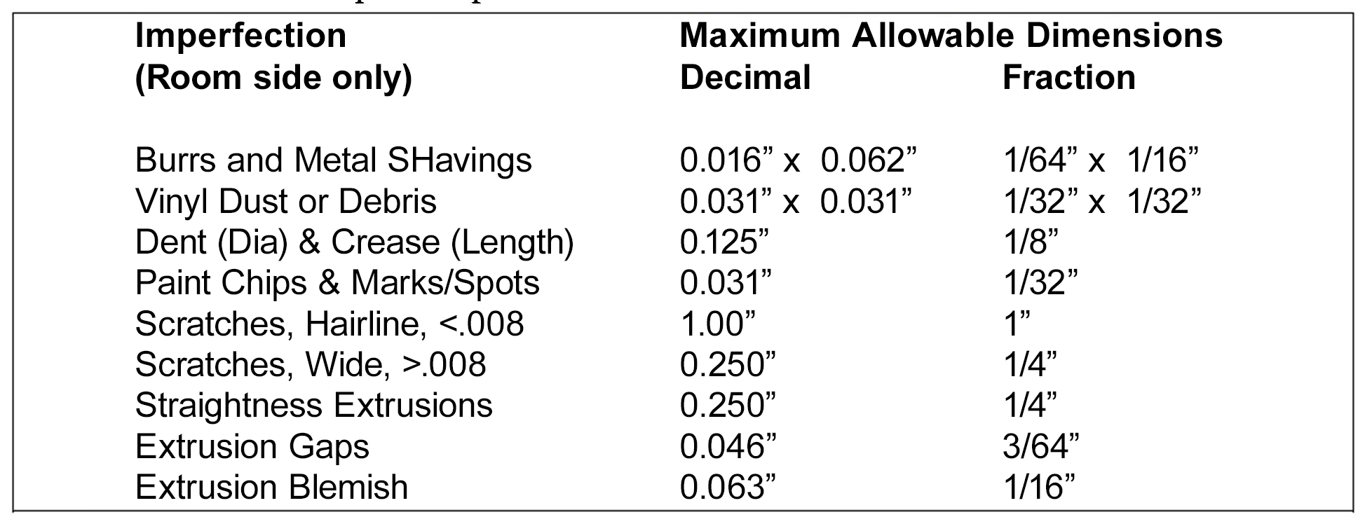
- Maximum allowable defects in the same vicinity not to exceed 2 within a 1" square area, no more than 3 defects within a 4" radius of other defects.
- This unit is gear driven. Therefore it is acceptable to feel the belt during operation.
- Slat marks on side rail and intercept cap appearing at top of unit are normal occurences which appear during shipping, unit's normal operation position is fully down.
- Lift and Tilt BBG. Sliding the Operator magnet up will lower the blind. When initially sliding the operator up, the slat will rotate closed with the slat crown facing outside. Sliding the Operator down will raise the blind. When initially sliding this side down the slat will rotate closed with the slat crown facing the inside. Small adjustments by moving the outside operator up or down will enable optimum slat tilting positioning.
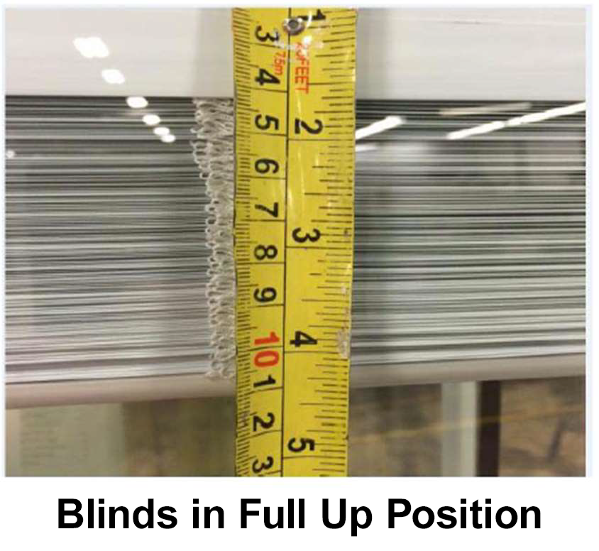
- When blinds are fully up, if you cannot see through the blinds, this is acceptable. Total length from top of glass to bottom of slat rail can deviate up to ¼" within an individual unit. For units that are side by side, such as in a patio door assembly, may vary ¾" between units.
- The bottom rail, when suspended or fully down may have some bow. For units ≤ 36" wide may bow up to ⅛" and for units > 36" wide up to 3/16".
Specifications:
BLIND APPEARANCE CRITERIA
OPERATION
BLINDS - UP
BOTTOM RAIL - SUSPENDED / DOWN
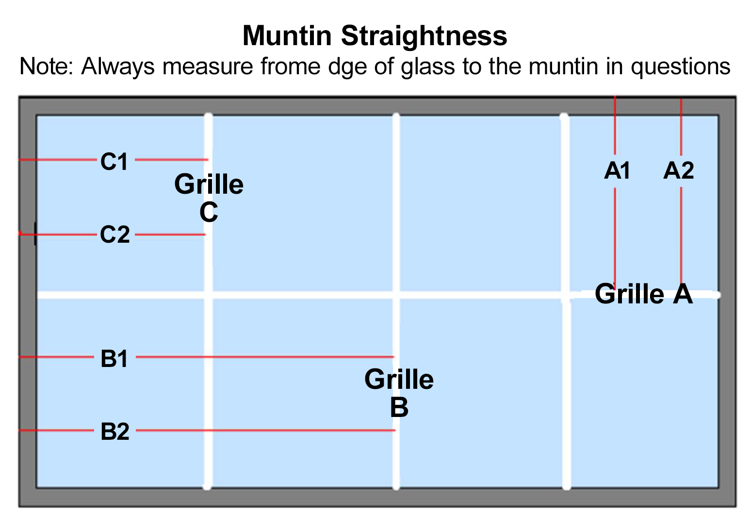
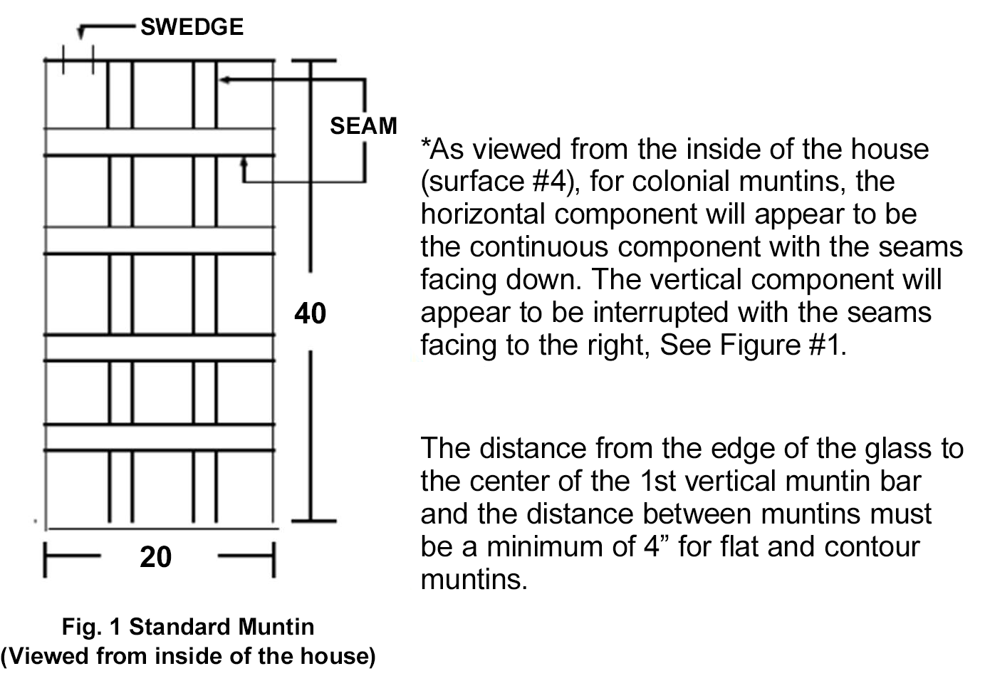
MUNTINS - BETWEEN GLASS STRAIGHTNESS
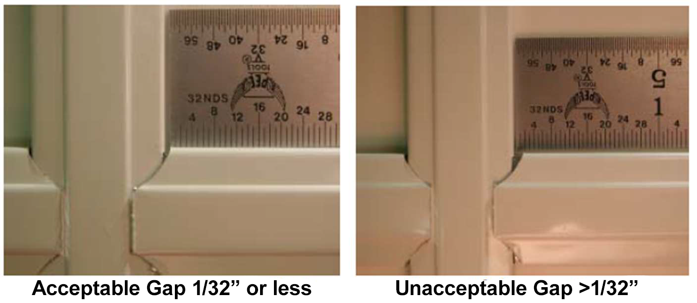
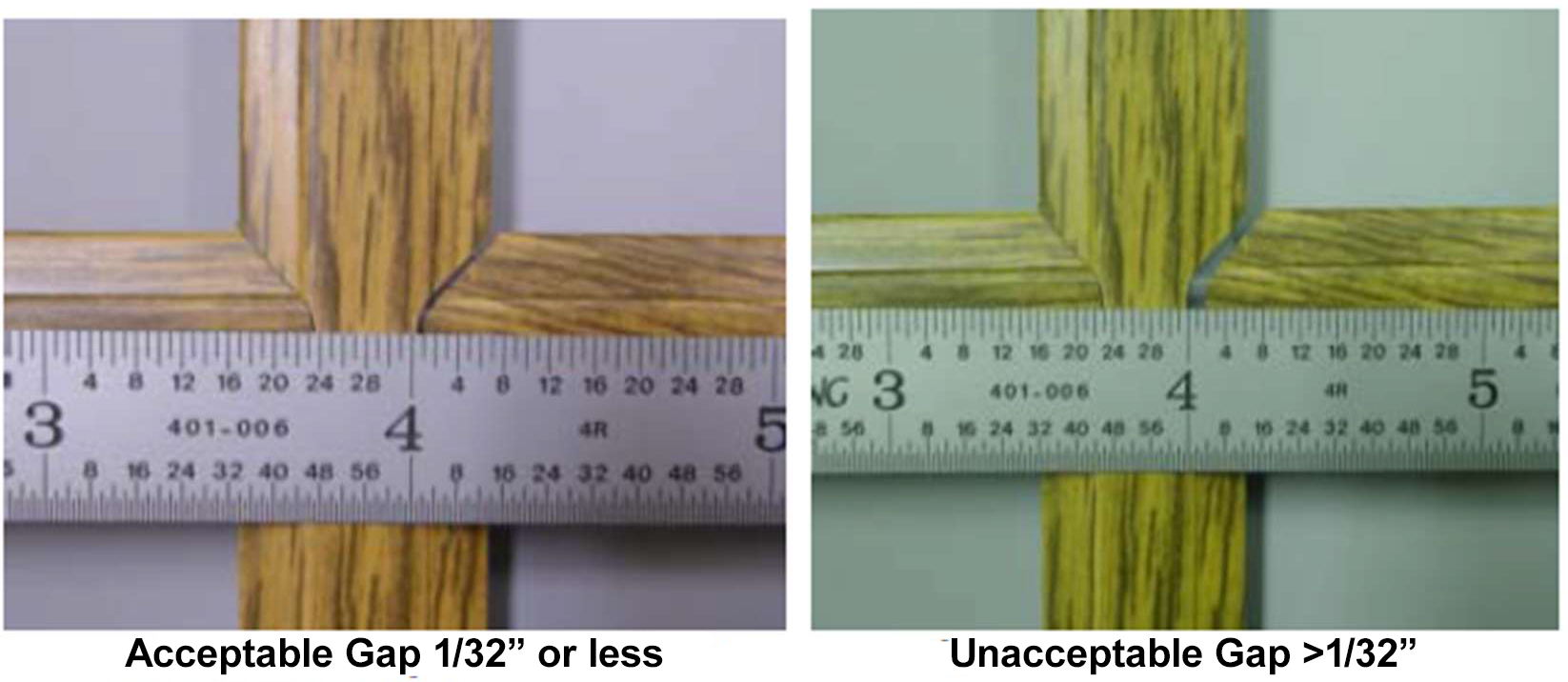
- Muntins are to be inspected visually first. Any muntin that appears to be out of alignment shall then be measured using a tape measure. Two measurements shall be taken for each muntin section that is questionable. Measure from the edge of glass to both ends of the muntin section in question. Straightness of muntin can be measured between each muntin intersection regardless of whether the muntin is continuous or non-continuous.
- Measurements shall always be taken from beginning at the edge of the glass to the muntin, not from muntin to muntin. The only exception to this is when the glass has a curved section to it. For these curved products, measurements can be made from muntin to muntin.
- Maximum allowable difference:
- Grilles up to 4" long = 1/32" (0.031").
- Grilles over 4" long = 1/16" (0.062").
- Each muntin bar has a seam on one edge of the muntin. This seam shall always be oriented down on horizontal muntins. Vertical muntins are allowed to have seam orientation left or right but not mixed (some left, some right) within any IG unit. Standard orientation is to the right when viewing from surface four.
- Unpainted ends are allowable.
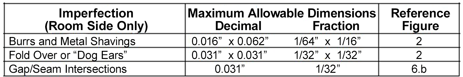
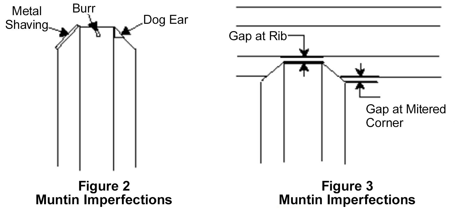
Muntin Appearance Criteria (visible at 36" or more):
CONTOUR GRID MACHINE CRITERIA
ROUTER MACHINE CONTOUR MUNTIN CRITERIA
- Have a tolerance of (+/-) 1/16" when measured with a tape measure.

- Have a tolerance of (+/-) ½" when measured with a tape measure from one corner to the opposite corner.
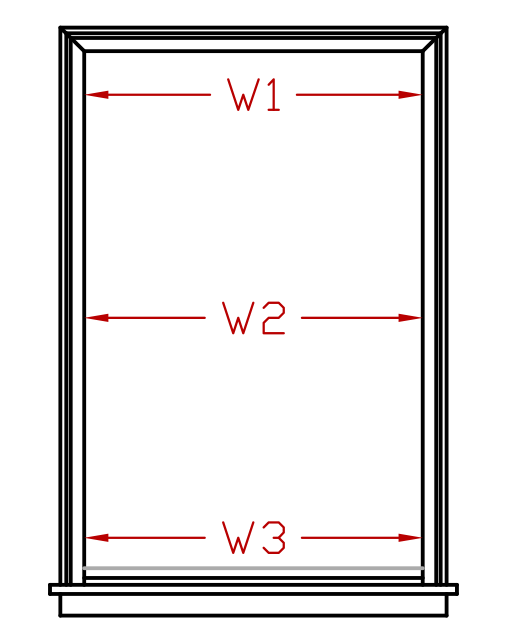
- Have a tolerance of (+/-) 1/16" when measured with a tape measure when measured horizontally across the top, middle and bottom of the screen.
- Less than 2" if the screen is smaller than 150 UI.
- Greater than 1" if the screen is larger than 150 UI.
- Measure by placing the screen on a flat surface, hold one corner down and measure the opposite corner with a ruler / tape measure.
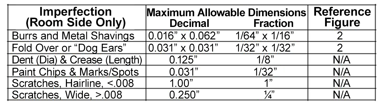
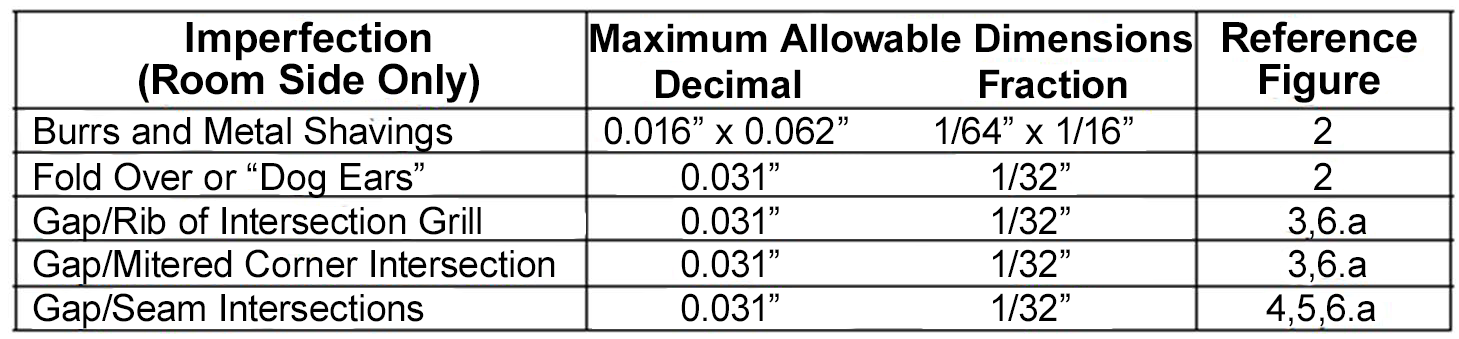
- No drill burr greater than 1/16" when measured with a 1/16" feeler gauge.
- 1/32" or less either across entire length of cut on tip or base of cut measured with a 1/32" feeler gauge.
- Tips of opposing pieces must align within 1/32" or less gap measured with a 1/32" feeler gauge.
- Hardware must move freely up, down, or side to side within the punched or drilled hole. Checks are performed by physical actuation testing of the hardware after installation.
- Spring must sit securely on the edge of material and be able to be compressed and released without falling off edge.
- (+/-) 1/16" from customer specified dimension measured with a tape measure.
- No more than ⅛" misalignment from edge of frame measured with a tape measure.
- Defect visible of any size within a 4 foot viewing distance. Defects with a repeated pattern are to be rejected. Perform visual inspection at 4 feet under ample (normal) lighting.
- No cuts or tears on the viewing surface. No more than one thread per 12" can be cut at spline channel edge. Inspect by viewing surface at arm's length. Spline channel viewing up to 6" from surface.
- No more than 1/32" visible deformation to the punch surface or adjoining edge appearing as a dimple, depression, or flair.
- Have a tolerance of (+/-) 1/16" when measured with a tape measure.
- Have a tolerance of (+/-) ½" when measured with a tape measure from one corner to the opposite corner.
- Have a tolerance of (+/-) 1/16" when measured with a tape measure when measured horizontally across the top, middle and bottom of the screen.
- Less than 2" if the screen is smaller than 150 UI.
- Greater than 1" if the screen is larger than 150 UI.
- Measure by placing the screen on a flat surface, hold one corner down and measure the opposite corner with a ruler / tape measure.
- No drill burr greater than 1/16" when measured with a 1/16" feeler gauge.
- 1/32" or less either across entire length of cut on tip or base of cut measured with a 1/32" feeler gauge.
- Tips of opposing pieces must align within 1/32" or less gap measured with a 1/32" feeler gauge.
- Hardware must move freely up, down, or side to side within the punched or drilled hole. Checks are performed by physical actuation testing of the hardware after installation.
- Spring must sit securely on the edge of material and be able to be compressed and released without falling off edge.
- (+/-) 1/16" from customer specified dimension measured with a tape measure.
- No more than ⅛" misalignment from edge of frame measured with a tape measure.
- Defect visible of any size within a 4 foot viewing distance. Defects with a repeated pattern are to be rejected. Perform visual inspection at 4 feet under ample (normal) lighting.
- No cuts or tears on the viewing surface. No more than one thread per 12" can be cut at spline channel edge. Inspect by viewing surface at arm's length. Spline channel viewing up to 6" from surface.
- No more than 1/32" visible deformation to the punch surface or adjoining edge appearing as a dimple, depression, or flair.
- (+/-) 1/16" from customer specified location < 80" door height (subtract) center handle. Over 80" = door height (subtract) 40" center or per customer's specification measured with a tape measure.
- Hole must be clear of all plastic or metal debris to head of adjustment screw, clearly visible and accessible.
- All wheels must be contained in wheel slot and engaged on corner retention ears. Verify by performing a physical push/pull test.
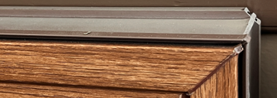
Exposed Vinyl on the Meeting Rail
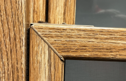
The bottom corner of the interlock on the top sash is cut away to allow for the bottom sash to operate freely. The channel behind the interlock is not covered with laminate and will be visible only when the bottom sash is raised. The is not a defect as the laminate is cut away in a normal manufacturing environment.
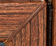
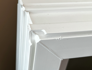
Painted Weld LinesThe corners of the frame and sash are welded together. After the wedling operation is complete, the weld seam will be painted to match the color of the laminate. There will be minor variations to the paint applied to each corner seam.
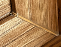
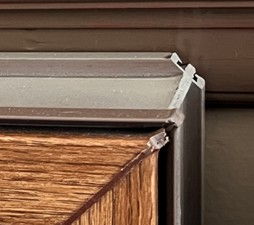
Exposed Vinyl on the Accessory GrooveThe laminate applied to a Polaris vinyl extrusion will cover the trim groove around the interior perimeter of the face. If a trim extrusion is required for the installation of the window, the groove will need to be opened to allow a trim piece to be allowed to snap into the groove, which may expose bare vinyl.
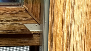
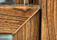
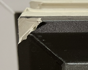
Corner NotchBrand new, uninstalled windows will have material removed from the corners. This is part of the manufacturing process to remove the excess flash after the frame has been welded, and will be covered after the window has been installed. The cutouts do not affect sealing or water mitigation.
Painted Weld Lines
Exposed Vinyl on the Accessory Groove
Corner Notch
- Linear Blemish - scratches, rubs, digs, and other similar imperfections, which may be straight or curved in nature; if curved, the length of such a blemish is to be measured from end to end along the curve.
- Point Blemish - crush, knots, dirt, stones, gaseous inclusions, tin drip, and other similar imperfections.
- Shell Chip - any chip other than a v-chip.
- V-Chip - a chip forming an acute angle, located at the edge(s) of a glass lite and which may cause a crack in the glass.